A Rotary Encoder is an electro mechanical device that converts angular movement of the shaft to analog or digital code.
Rotary Encoders can be found in radio equipment like amateur radio or hand held, where non-stop or continuous 3600 rotation is required for tuning to right frequency.
In this project, the working of Rotary Encoder is explained with the
help of Arduino. The following sections are dived into introduction to
rotary encoders, circuit and working.
Table of Contents
Circuit Diagram
Hardware Required
Rotary Encoder
Arduino UNO
LCD Display
Introduction to Rotary Encoders
A Rotary Encoder is an input device that provides the information
about the direction and amount of rotation of the knob. There is a
select switch associated with the rotary encoders that can be activated
by pushing the knob.
The commonly used rotary encoder is an incremental rotary encoder.
This type provides an instantaneous result about the rotating shaft by
generating two square wave outputs that are 90 degrees out of phase with
each other.
A rotary encoder has to coding pins A and B produce either High or
Low output depending on the rotation and direction of the shaft.
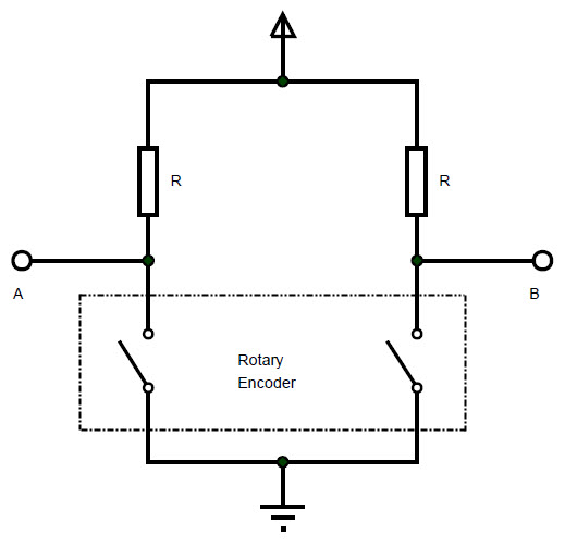
The basic function of a rotary encoder can be explained by
considering it as a combination of two switches that close or open due
to rotation of the shaft.
As
the shaft rotates, the switches are closed and opened in a pattern. If
the outputs are treated as binary, then for clock wise rotation, the
outputs at A and B will be 00, 01, 11 and 10.
For anticlockwise or counter clockwise rotation, the outputs will be
10, 11, 01 and 00. The waveform of the pulses in both directions of
rotation is shown below.
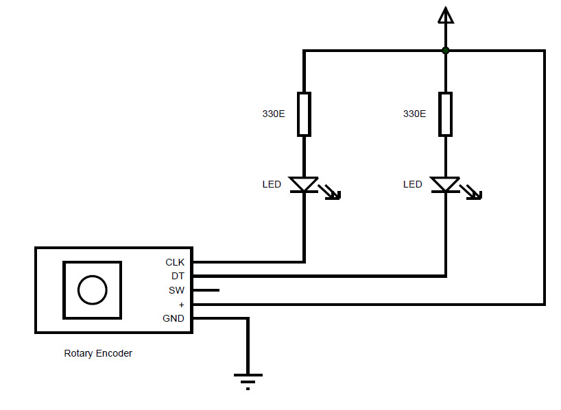
To test the sequence, the output pins of the rotary encoder are connected to two LEDs as shown in the following circuit.
When the knob of the rotary encoder is rotated in clockwise or anti
clockwise directions, the LEDs light up as per the above mentioned
sequence.
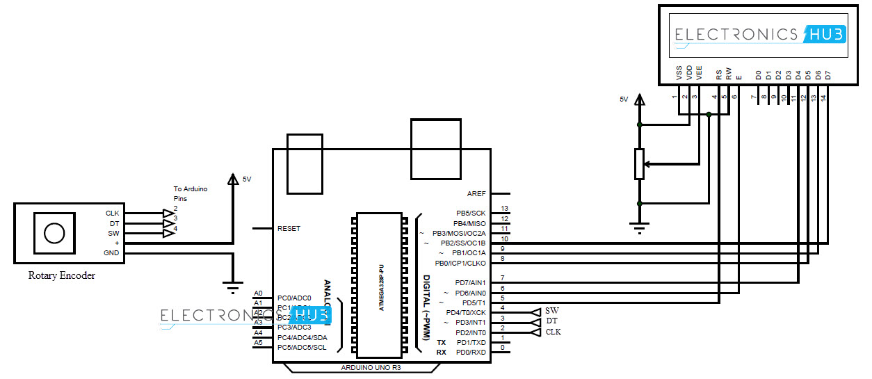
Circuit design of Rotary Encoder with Arduino
Rotary Encoder consists of five pins: two coding pins A and B (or CLK
and DT), one pin for switch and two power supply pins for Vcc and GND.
The two coding pins and the switch pin provide digital signals. They are connected to pins 2, 3 and 4 of Arduino.
To display the objects of the menu, a 20X4 LCD display is used. The
connections are similar to that of 16X2 LCD. RS and E of LCD are
connected to pins 5 and 6 of Arduino.
The data pins i.e. D4 – D7 (pins 11 – 14) of LCD are connected to pins 7 – 10 of Arduino.
Working
Rotary Encoders provide infinite rotation in either direction with a
select button (pushing the knob). Such unique functionality can be used
in “menu” selection applications, where the rotation of shaft in either
direction will allow us to browse the contents of the menu and push of
the button will allow us to select the highlighted menu content.
In this project, the working of rotary encoder as a menu selector is
explained with the help of Arduino and LCD. The working of the circuit
is as follows.
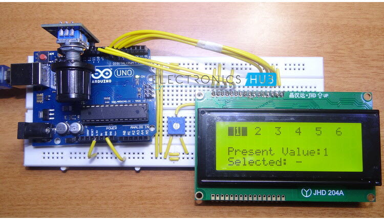
The code for Arduino is written as per the application and uploaded
to Arduino. On power up, the LCD displays the list of values
horizontally.
By rotating the shaft of the rotary encoder in clockwise direction,
the menus items will change from left to right with each item being
highlighted for every turn of the knob.
Once the last item is reached, further rotation will not result in any action but the last item will be highlighted.
If the knob is rotated in anti-clockwise direction, the menus items
will be highlighted in reverse direction. The highlighted item will be
displayed below the list of items.
If we want to select any highlighted item, the button of the rotary
encoder is pushed. This is shown as the selected item and the selected
item stays that way until the next item is selected.
More and more makerspaces around the world are looking to add coding and electronics to their maker education programs. One of the best ways to do this is by integrating an Arduino board into makerspace projects and lessons. We’ve found that a lot of maker educators haven’t taken the plunge into coding or Arduino because they think programming is scary. Because of this, we wanted to make sure this tutorial was written for the absolute beginner with no experience whatsoever. This tutorial is a high level view of all the parts and pieces of the Arduino ecosystem. In future posts, we will take you step by step in creating your first simple Arduino project. What Is Arduino? Arduino is an open source programmable circuit board that can be integrated into a wide variety of makerspace projects both simple and complex. This board contains a microcontroller which is able to be programmed to sense and control objects in the physi...
GSM Based Home Security Alarm System Using Arduino Home Security Systems are an important feature of modern residential and office setups. Home security systems must be affordable, reliable and effective. Modern complex home security systems include several security features like fire, intruders, electronic door lock, heat, smoke, temperature, etc. Some security systems may be a combination of all the security measures. Such complex systems may be expensive and may not be affordable by everyone. There are individual security systems based on the requirement. In this project, we designed a simple but very efficient home security that has a function of calling the homeowner on his/her mobile number in case of an intruder alert. Help us in selecting the next DIY Arduino Project. : Select your Favourite Project » The project is based on Arduino, PIR motion detection sensor and GSM Module. Table of Contents Circuit Diagram Hardware Required Circuit ...
Arduino Solar Tracker In modern solar tracking systems, the solar panels are fixed on a structure that moves according to the position of the sun. Let us design a solar tracker using two servo motors, a light sensor consisting of four LDRs and Arduino UNO board. Table of Contents Circuit Diagram Components Required Working Setup Project Code Circuit Diagram The circuit design of solar tracker is simple but setting up the system must be done carefully. Four LDRs and Four 100KΩ resistors are connected in a voltage divider fashion and the output is given to 4 Analog input pins of Arduino. The PWM inputs of two servos are given from digital pins 9 and 10 of Arduino. Components Required Arduino UNO [ Buy Here ] Servo Motor [ Buy Here ] Light Sensors LDR Resistors Working LDRs are used as the main light sensors. Two servo motors are fixed to the structure that holds the solar panel. The program for Arduino is uploaded to the microcontroller. Th...
 As
the shaft rotates, the switches are closed and opened in a pattern. If
the outputs are treated as binary, then for clock wise rotation, the
outputs at A and B will be 00, 01, 11 and 10.
As
the shaft rotates, the switches are closed and opened in a pattern. If
the outputs are treated as binary, then for clock wise rotation, the
outputs at A and B will be 00, 01, 11 and 10.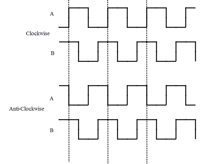


Comments
Post a Comment