GSM Based Home Security Alarm System Using Arduino
Get link
Facebook
X
Pinterest
Email
Other Apps
-
GSM Based Home Security Alarm System Using Arduino
Home
Security Systems are an important feature of modern residential and
office setups. Home security systems must be affordable, reliable and
effective.
Modern complex home security systems include several security
features like fire, intruders, electronic door lock, heat, smoke,
temperature, etc. Some security systems may be a combination of all the
security measures.
Such complex systems may be expensive and may not be affordable by
everyone. There are individual security systems based on the
requirement.
In this project, we designed a simple but very efficient home
security that has a function of calling the homeowner on his/her mobile
number in case of an intruder alert.
SIM 900A (or any other) GSM Module with SIM inserted
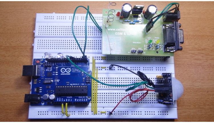
Circuit Design of Arduino GSM Home Security Alarm System
As the project is based on an Arduino, the connection is pretty
simple. PIR motion detection sensor module has a digital output pin.
This is connected to any of the digital I/O pins of the Arduino.
The GSM Module communicates with the microcontroller in a serial
manner. It has an Rx and Tx pins on the board. These pins are connected
to the Tx and Rx pins of the Arduino.
It is important to note that while uploading the program (sketch) to
Arduino, the GSM module must be disconnected as it might interfere with
the serial communication with the Arduino IDE.
Component Description
PIR Motion Detection Sensor
Passive Infra-Red or PIR Sensor is a Pyroelectric device that detects
motion. Hence, it is also called as motion detection sensor. It detects
motion by sensing the changes in infrared levels emitted by nearby
objects.
GSM Module (SIM 900A)
SIM 900A is the GSM/GPRS module with built in RS232 interface. It has
dual band GSM/GPRS system that works on 900/1800MHz frequencies.
With the help of RS232, the modem can be connected to PC or
microcontroller via serial cable. Voice calls, SMS and internet access
are possible with this module.
There are on board connections for microphone and headphones with which we can make or receive calls.
Arduino UNO
It is the main controller used in this project. It detects the
signals from PIR sensor and sends commands to GSM Module accordingly.
The serial pins of the Arduino are used in this project to communicate
with GSM module.
Working of Arduino GSM Home Security Alarm System
Home Security Alarm Systems are very important in present day
society, where crime is increasing. With the technological advancements
we have achieved in the recent years, a homeowner doesn’t have to worry
about home security while getting off his/her home.
Modern home security systems provide enough security from burglars,
fire, smoke, etc. They also provide immediate notification to the
homeowner.
The aim of this project is to implement a simple and affordable, but
efficient home security alarm system. The project is designed for
detecting intruders and informing the owner by making a phone call.
The working of the project is explained below.
PIR sensor detects motion by sensing the difference in infrared or
radiant heat levels emitted by surrounding objects. The output of the
PIR sensor goes high when it detects any motion. The range of a typical
PIR sensor is around 6 meters or about 30 feet.
For proper operation of PIR sensor, it requires a warm up time of 20
to 60 seconds. This is required because, the PIR sensor has a settling
time during which it calibrates its sensor according to the environment
and stabilizes the infrared detector.
During this time, there should be very little to no motion in front
of the sensor. If the sensor is not given enough calibrating time, the
output of the PIR sensor may not be reliable.
When the PIR sensor detects any motion, the output of the sensor is
high. This is detected by the Arduino. Arduino then communicates with
the GSM module via serial communication to make a call to the pre
programmed mobile number.
An important point to be noted about PIR sensors is that the output
will be high when it detects motion. The output of the sensor goes low
from time to time, even when there is motion which may mislead the
microcontroller into considering that there is no motion.
This issue must be dealt with in the programming of Arduino by
ignoring the low output signals that have a shorter duration than a
predefined time. This is done by assuming that the motion in front of
PIR sensor is present continuously.
Code
int LED1=12;
int GND1=13;
int LED2=8;
int GND2=9;
int pirOutput=5;
void setup()
{
Serial.begin(9600);
pinMode(LED1,OUTPUT);
pinMode(GND1,OUTPUT);
pinMode(LED2,OUTPUT);
pinMode(GND2,OUTPUT);
pinMode(pirOutput,INPUT);
digitalWrite(pirOutput,LOW);
digitalWrite(GND1,LOW);
digitalWrite(GND2,LOW);
digitalWrite(LED1,LOW);
digitalWrite(LED2,LOW);
delay(15000);
digitalWrite(LED1,HIGH);
}
void loop()
{
if(digitalRead(pirOutput)==HIGH)
{
digitalWrite(LED2,HIGH);
Serial.println("OK");
delay(1000);
Serial.println("ATD+91xxxxxxxxxx;");//add target mobile number in place of xxxxxxxxxx
delay(15000);
Serial.println("ATH");
digitalWrite(LED2,LOW);
delay(1000);
}
}
NOTE
A GSM based home security alarm system is designed using Arduino, PIR motion detection sensor and a GSM module.
When the system is activated, it continuously checks for motion and
when the motion is detected, it make a phone call to the owner.
Only intruder alert is present in this system and can be upgraded to other security alert systems like fire, smoke etc.
More and more makerspaces around the world are looking to add coding and electronics to their maker education programs. One of the best ways to do this is by integrating an Arduino board into makerspace projects and lessons. We’ve found that a lot of maker educators haven’t taken the plunge into coding or Arduino because they think programming is scary. Because of this, we wanted to make sure this tutorial was written for the absolute beginner with no experience whatsoever. This tutorial is a high level view of all the parts and pieces of the Arduino ecosystem. In future posts, we will take you step by step in creating your first simple Arduino project. What Is Arduino? Arduino is an open source programmable circuit board that can be integrated into a wide variety of makerspace projects both simple and complex. This board contains a microcontroller which is able to be programmed to sense and control objects in the physi...
Arduino Solar Tracker In modern solar tracking systems, the solar panels are fixed on a structure that moves according to the position of the sun. Let us design a solar tracker using two servo motors, a light sensor consisting of four LDRs and Arduino UNO board. Table of Contents Circuit Diagram Components Required Working Setup Project Code Circuit Diagram The circuit design of solar tracker is simple but setting up the system must be done carefully. Four LDRs and Four 100KΩ resistors are connected in a voltage divider fashion and the output is given to 4 Analog input pins of Arduino. The PWM inputs of two servos are given from digital pins 9 and 10 of Arduino. Components Required Arduino UNO [ Buy Here ] Servo Motor [ Buy Here ] Light Sensors LDR Resistors Working LDRs are used as the main light sensors. Two servo motors are fixed to the structure that holds the solar panel. The program for Arduino is uploaded to the microcontroller. Th...
 Hardware Required


Comments
Post a Comment