A
Light Sensor is a device that detects light. It generates an output
signal that is proportional to the intensity of light. A light sensor
measures the radiant energy present in the wide range of frequencies in
the light spectrum. Some of the common frequencies are infrared, visible
and ultraviolet.
A Light Sensor is also called as Photo Sensor or Photo electric
Sensor as it converts light energy or photons in to electrical signals.
There are different types of light sensors
for different applications. A Photocell or Photo Resistor is the common
type of light sensor.
A photo resistor changes its resistance when light is incident on it.
Hence, a photo resistor is also called as Light Dependent Resistor or
LDR.
When there is no light, the resistance of LDR is very high. When there is light incident on the LDR, its resistance decreases.
There are a wide range of applications of light sensors. The
applications include scientific research to everyday residential
applications like security systems, burglar alarms garage door openers,
solar tracking systems etc.
In this project, a simple light sensor is designed using LDR. The
project is built around Arduino. The circuit, components and working are
mentioned in the following sections.
An LDR is a type of variable resistor that change its resistance
according to intensity of the light incident on it. Generally, when the
intensity of light is less i.e. in dark conditions, the resistance of
LDR will be in the order of Mega Ohms (MΩ).
As the intensity of the light increases, it resistance decreases and falls down to few Ohms at maximum intensity of light.
Photo Resistors are semiconductor devices with photo sensitive cells.
Photo cells are made with different compounds depending on the
frequency of the light and application they are used.
Cadmium Sulphide cell based photo resistors are most common in
consumer applications as they are inexpensive. Some applications are
night lights, alarm systems, solar tracking systems etc.
Lead Sulphide and Indium Antimonide cell based photo resistors are frequently used for low to mid infrared frequencies.
Germanium Copper cell based light dependent resistors are used in far
infrared frequency applications and they are used in infrared based
astronomy and spectroscopy.
100 KΩ Potentiometer
This is a variable resistor whose resistance can be varied from 0Ω to 100 KΩ.
Arduino UNO
It is the main controlling part of the project. It has both analog
and digital pins. It has 6 analog input pins and 14 digital I/O pins.
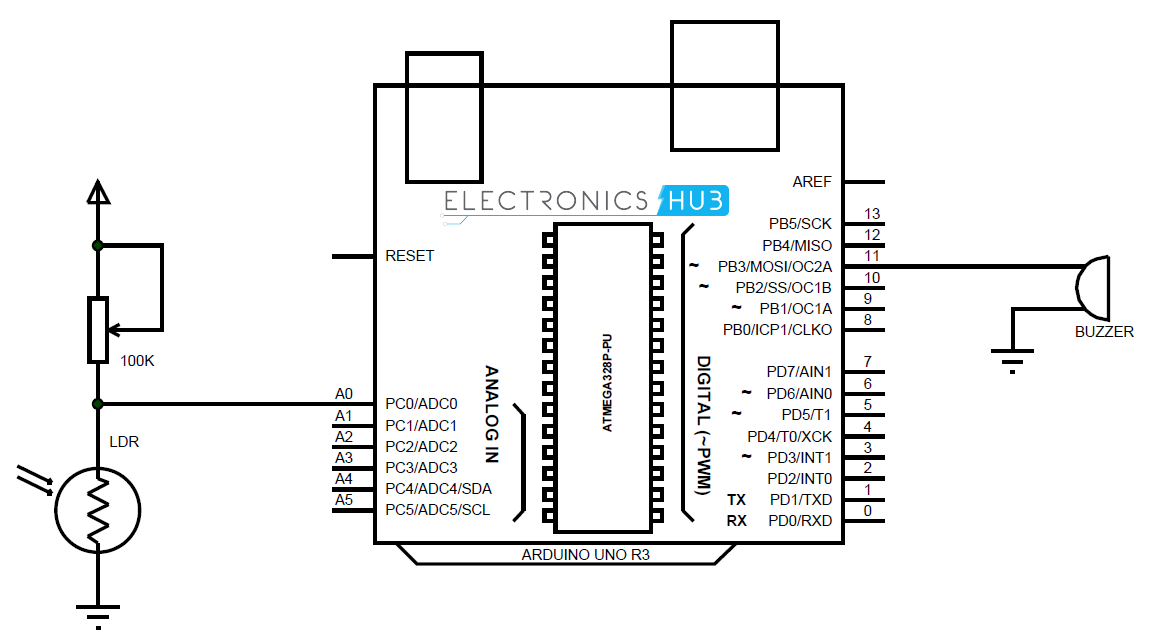
Circuit Design of Light Sensor
As the photo resistor or LDR is a variable resistor, a voltage
divider network must be used to gets the analog equivalent output from
it.
A 100 KΩ POT and the LDR form a voltage divider and the output of the
voltage divider is given to the analog input A0 of Arduino.
A buzzer is connected to pin 11 of Arduino.
Working of Arduino Light Sensor
Light Sensors are very useful devices in wide range of applications.
One of the common application is an automatic night lamp, where a light
bulb is automatically turned on as soon as the sun sets down.
Another good application is solar tracker, which tracks the sun and rotates the solar panel accordingly.
All these applications use a simple photo resistor or an LDR as the
main sensing device. Hence, in this project, we designed a simple light
sensor that indicates when the light is indicated. The working of the
project is very simple and is explained below.
All the connections are made as per the circuit diagram. The code for
Arduino is written and dumped in the board. When the LDR detects a
light over certain intensity, the Arduino will trigger the buzzer. When
the intensity of light decreases, the buzzer is turned off.
The 100 KΩ POT used in the voltage divider network can be used to adjust the intensity levels at which the buzzer is triggered.
Code
int sensorPin = A0; // select the input pin for the potentiometer
//int ledPin = 13; // select the pin for the LED
int sensorValue = 0; // variable to store the value coming from the sensor
void setup() {
// declare the ledPin as an OUTPUT:
Serial.begin(9600);
pinMode(ledPin, OUTPUT);
pinMode(11,OUTPUT);
}
/*void loop() {
// read the value from the sensor:
sensorValue = analogRead(sensorPin);
// turn the ledPin on
digitalWrite(ledPin, HIGH);
// stop the program for <sensorValue> milliseconds:
delay(sensorValue);
// turn the ledPin off:
digitalWrite(ledPin, LOW);
// stop the program for for <sensorValue> milliseconds:
delay(sensorValue);
}*/
void loop()
{
sensorValue=analogRead(sensorPin);
if(sensorValue <= 14)
digitalWrite(11,HIGH);
else
digitalWrite(11,LOW);
Serial.println(sensorValue);
delay(2);
}
Applications
Light Sensors are used in variety of applications.
They can be used in security systems like burglar alarm systems
where an alarm is triggered when the light falling on the sensor is
interrupted.
Another common application of light sensor is night lamp. As long as
the sun light falls on the light sensor, the lamp will be switched off.
When the sun light starts decreasing and is completely off, the lamp
will be turned on automatically.
One of the important applications of light sensors is in generation
of efficient solar energy. Light sensors are often used in Solar
Tracking systems. The solar panel will be rotated according to the
movement of the sun and its intensity.
More and more makerspaces around the world are looking to add coding and electronics to their maker education programs. One of the best ways to do this is by integrating an Arduino board into makerspace projects and lessons. We’ve found that a lot of maker educators haven’t taken the plunge into coding or Arduino because they think programming is scary. Because of this, we wanted to make sure this tutorial was written for the absolute beginner with no experience whatsoever. This tutorial is a high level view of all the parts and pieces of the Arduino ecosystem. In future posts, we will take you step by step in creating your first simple Arduino project. What Is Arduino? Arduino is an open source programmable circuit board that can be integrated into a wide variety of makerspace projects both simple and complex. This board contains a microcontroller which is able to be programmed to sense and control objects in the physi...
GSM Based Home Security Alarm System Using Arduino Home Security Systems are an important feature of modern residential and office setups. Home security systems must be affordable, reliable and effective. Modern complex home security systems include several security features like fire, intruders, electronic door lock, heat, smoke, temperature, etc. Some security systems may be a combination of all the security measures. Such complex systems may be expensive and may not be affordable by everyone. There are individual security systems based on the requirement. In this project, we designed a simple but very efficient home security that has a function of calling the homeowner on his/her mobile number in case of an intruder alert. Help us in selecting the next DIY Arduino Project. : Select your Favourite Project » The project is based on Arduino, PIR motion detection sensor and GSM Module. Table of Contents Circuit Diagram Hardware Required Circuit ...
Arduino Solar Tracker In modern solar tracking systems, the solar panels are fixed on a structure that moves according to the position of the sun. Let us design a solar tracker using two servo motors, a light sensor consisting of four LDRs and Arduino UNO board. Table of Contents Circuit Diagram Components Required Working Setup Project Code Circuit Diagram The circuit design of solar tracker is simple but setting up the system must be done carefully. Four LDRs and Four 100KΩ resistors are connected in a voltage divider fashion and the output is given to 4 Analog input pins of Arduino. The PWM inputs of two servos are given from digital pins 9 and 10 of Arduino. Components Required Arduino UNO [ Buy Here ] Servo Motor [ Buy Here ] Light Sensors LDR Resistors Working LDRs are used as the main light sensors. Two servo motors are fixed to the structure that holds the solar panel. The program for Arduino is uploaded to the microcontroller. Th...
 Hardware Required


Comments
Post a Comment