In
this project, we designed an Arduino based Real Time Clock with alarm. A
Real Time Clock or RTC is a battery powered clock that measures time
even when there is no external power or the microcontroller is
reprogrammed.
An RTC displays clock and calendar with all timekeeping functions.
The battery, which is connected to the RTC is a separate one and is not
related or connected to the main power supply.
When the power is restored, RTC displays the real time irrespective
of the duration for which the power is off. Such Real Time Clocks are
commonly found in computers and are often referred to as just CMOS
(Complementary Metal Oxide Semiconductor).
Most microcontrollers and microprocessors have built in timers for
keeping time. But they work only when the microcontroller is connected
to power supply.
When the power is turned on, the internal timers reset to 0. Hence, a
separate RTC chip is included in applications like data loggers for
example, which doesn’t reset to 0 when the power is turned off or reset.
Real Time Clocks are often useful in data logging applications, time
stamps, alarms, timers, clock builds etc. In this project, a Real Time
Clock, which displays accurate time and date along with an alarm feature
is designed.
One of the frequently used RTC ICs DS1307 is used in this project
along with Arduino. The circuit, design and working are explained in the
following sections.
DS1307 is the frequently used real time clock (RTC) IC for clock and
calendar. The clock function provides seconds, minutes and hours while
the calendar function provides day, date, month and year values.
The clock can operate in either 12 hour with AM/PM indication or 24
hour format. A 3V backup battery must be connected to the RTC so that
the IC can automatically switch to the backup supply in case of power
failure. A
32.768 KHz crystal is connected to the oscillator terminal of DS1307 for 1 Hz oscillations.
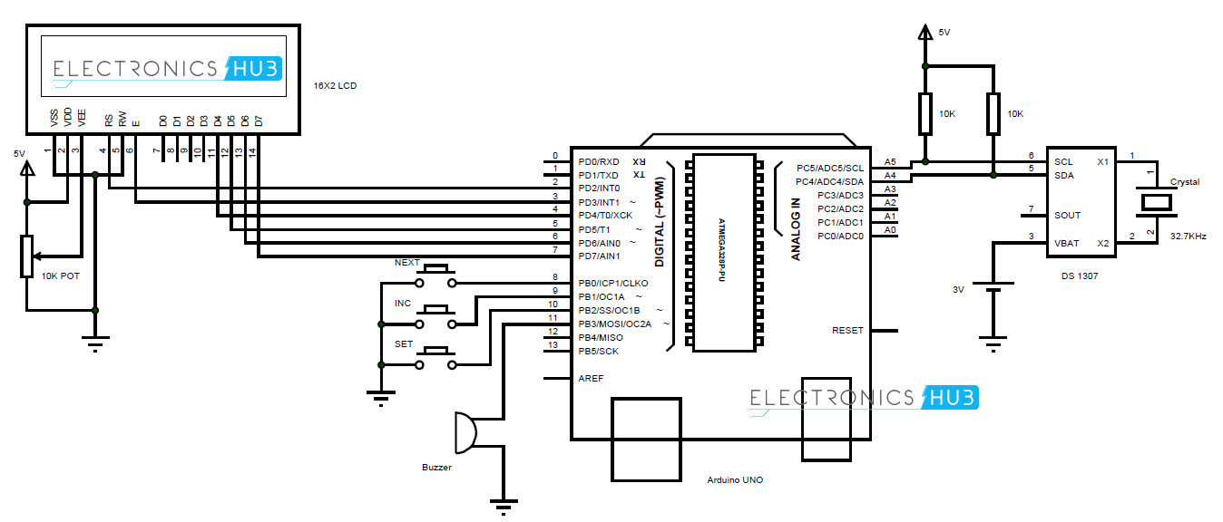
Circuit Design
The communication between microcontroller and RTC IC DS1307 is serial
I2C bidirectional bus. I2C protocol is a method of communication
between a faster device (Microcontroller or Arduino in this case) in
master mode and a slower device (RTC) in slave mode.
There are two pins on Arduino for I2C communication. Analog pins 4 and 5 will act as SDA (Serial Data) and SCL (Serial Clock).
These are connected to respective SDA and SCL pins of RTC. Both these pins of RTC are pulled high using 10KΩ resistors.
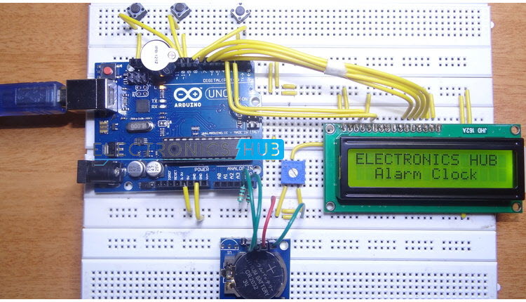
An LCD is used to display the clock. 6 pins of LCD must be connected
to Arduino. RS, E, D4, D5, D6 and D7 (Pins 4, 6, 11, 12, 13 and 14) of
LCD are connected to pins 2, 3, 4, 5, 6 and 7 of Arduino.
Three buttons are used to set the alarm. These buttons are connected
to pins 8, 9 and 10 of Arduino. A buzzer is connected to pin 11 of
Arduino that acts as an alarm.
Working
The aim of this project is to create a real time clock along with an
alarm feature. The working of the project is explained below.
All the connections are made as per the shown circuit diagram. The
code for Arduino is uploaded and the LCD displays the current date and
time.
In order to set the alarm, we press the set button. It’ll go to alarm
mode and asks for hours with current time being displayed. The
increment button must be pressed must be pressed to change the hours.
As the clock is in 24 hour format, the hours will be incremented
between 0 and 23. Once the hours of the alarm is set, we must press the
next button to go to minutes tab.
Again increment button is pressed to change the minutes. Once the
alarm time is entered, set button is pressed and the alarm is set.
The values entered as alarm are stored in the EEPROM of the Arduino.
These values are continuously compared with the present time.
When the stored values and current value match, the buzzer for the
alarm will be triggered. In order to stop the alarm, the next button is
pressed.
Output Video
Code
#include <Wire.h>
#include<EEPROM.h>
#include <RTClib.h>
#include <LiquidCrystal.h>
LiquidCrystal lcd(2, 3, 4, 5, 6, 7);
RTC_DS1307 RTC;
int tmp,Inc,hor,mIn,add=11;
int set=8;
int cge=9;
int mod=10;
int off=0;
#define buz 11
int Hor,Min,Sec;
///////////////////////////////////////Function to adjust the time//////////////////////////////////
void time()
{
int tmp=1,mins=0,hors=0,secs=0;
while(tmp==1)
{
off=0;
if(digitalRead(cge)==0)
{
Hor++;
if(Hor==24)
{
Hor=0;
}
}
lcd.clear();
lcd.setCursor(0,0);
lcd.print("Set Alarm Time ");
lcd.setCursor(0,1);
if(Hor<=9)
lcd.print("0");
lcd.print(Hor);
lcd.print(":");
lcd.print(Min);
lcd.print(":");
lcd.print(Sec);
delay(200);
lcd.setCursor(0,1);
lcd.print(" ");
lcd.print(":");
lcd.print(Min);
lcd.print(":");
lcd.print(Sec);
delay(200);
if(digitalRead(set)==0)
{
hor=Hor;
EEPROM.write(add++,hor);
tmp=2;
while(digitalRead(set)==0);
}
}
while(tmp==2)
{
if(digitalRead(cge)==0)
{
Min++;
if(Min==60)
{Min=0;}
}
lcd.setCursor(0,1);
lcd.print(Hor);
lcd.print(":");
if(Min<=9)
lcd.print("0");
lcd.print(Min);
lcd.print(":");
lcd.print(Sec);
lcd.print(" ");
delay(200);
lcd.setCursor(0,1);
lcd.print(Hor);
lcd.print(":");
lcd.print(" ");
lcd.print(":");
lcd.print(Sec);
lcd.print(" ");
delay(200);
if(digitalRead(set)==0)
{
mIn=Min;
EEPROM.write(add++, mIn);
tmp=0;
while(digitalRead(set)==0);
}
}
off=1;
delay(10);
}
///////////////////////////////////////////function to sound the buzzer//////////////////////////////////
void Buz()
{
if(digitalRead(set)==0)
off=0;
if(off==1)
{
digitalWrite(buz,HIGH);
delay(500);
digitalWrite(buz, LOW);
delay(500);
}
}
//////////////////////////////////////////function to compare the alarm time with current RTC time//////////////////
More and more makerspaces around the world are looking to add coding and electronics to their maker education programs. One of the best ways to do this is by integrating an Arduino board into makerspace projects and lessons. We’ve found that a lot of maker educators haven’t taken the plunge into coding or Arduino because they think programming is scary. Because of this, we wanted to make sure this tutorial was written for the absolute beginner with no experience whatsoever. This tutorial is a high level view of all the parts and pieces of the Arduino ecosystem. In future posts, we will take you step by step in creating your first simple Arduino project. What Is Arduino? Arduino is an open source programmable circuit board that can be integrated into a wide variety of makerspace projects both simple and complex. This board contains a microcontroller which is able to be programmed to sense and control objects in the physi...
GSM Based Home Security Alarm System Using Arduino Home Security Systems are an important feature of modern residential and office setups. Home security systems must be affordable, reliable and effective. Modern complex home security systems include several security features like fire, intruders, electronic door lock, heat, smoke, temperature, etc. Some security systems may be a combination of all the security measures. Such complex systems may be expensive and may not be affordable by everyone. There are individual security systems based on the requirement. In this project, we designed a simple but very efficient home security that has a function of calling the homeowner on his/her mobile number in case of an intruder alert. Help us in selecting the next DIY Arduino Project. : Select your Favourite Project » The project is based on Arduino, PIR motion detection sensor and GSM Module. Table of Contents Circuit Diagram Hardware Required Circuit ...
Arduino Solar Tracker In modern solar tracking systems, the solar panels are fixed on a structure that moves according to the position of the sun. Let us design a solar tracker using two servo motors, a light sensor consisting of four LDRs and Arduino UNO board. Table of Contents Circuit Diagram Components Required Working Setup Project Code Circuit Diagram The circuit design of solar tracker is simple but setting up the system must be done carefully. Four LDRs and Four 100KΩ resistors are connected in a voltage divider fashion and the output is given to 4 Analog input pins of Arduino. The PWM inputs of two servos are given from digital pins 9 and 10 of Arduino. Components Required Arduino UNO [ Buy Here ] Servo Motor [ Buy Here ] Light Sensors LDR Resistors Working LDRs are used as the main light sensors. Two servo motors are fixed to the structure that holds the solar panel. The program for Arduino is uploaded to the microcontroller. Th...
 Components Required


Comments
Post a Comment