In
this project, we will learn about LED Matrix Displays and two different
projects on Arduino 8×8 LED Matrix Interface. The first project will be
a simple interface between Arduino and 8X8 LED Matrix to display
information (even scrolling information and images can be displayed) and
the second project will be an advanced project where the 8×8 LED Matrix
is controlled through an Android device.
An LED matrix is a two dimensional array of LEDs that can be used to
display symbols, characters or even images. Based on the orientation of
the LEDs in the matrix, there can be two types of LED matrices.They are
Common Row Anode and Common Row Cathode.
LED
matrix modules are one of the commonly used display devices and are
used in major applications like electronic display panels and
notification systems.
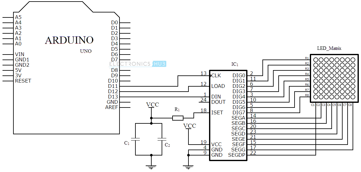
The project is based on the Arduino Uno microcontroller board. Out of
the 14 available digital input / output pins on the Arduino Uno, we
need only three pins to implement this project.
One pin provides the clock signal to the LED display driver IC (MAX
7219) while another pin is used to transmit the serial data to the IC
for displaying on the LED matrix. The corresponding pins must be
appropriately mentioned in the program.
LED Matrix
An 8 x 8 LED matrix display is used in this project to display the
information. LED matrices are available in different styles like single
color, dual color, multi-color or RGB LED matrix.
They are also available in different dimensions like 5 x 7, 8 x 8, 16
x 16, 32 x 32 etc. Based on the arrangement of the LEDs in the matrix,
an LED matrix can be either common row anode or common row cathode.
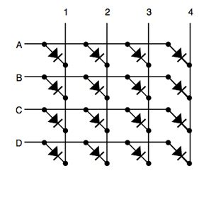
In case of common row anode type LED matrix, the current sources
(high or positive voltage) are given to the rows A-D and the current
sinks (low or negative voltage or ground) are given to the columns 1-4.
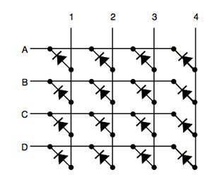
In case of common row cathode type LED matrix, the current sources
(high or positive voltage) are given to the columns 1-4 and the current
sinks (low or negative voltage or ground) are given to the rows A-D.
The LED matrix used in this project is a common row cathode type LED
matrix. While developing the project, the type of LED matrix must be
known and the program must be written accordingly.
IC MAX 7219
The LED matrix can be driven in two ways. They are parallel (where
each row or column are sent with parallel data) and serial (where the
data is sent serially and an IC is used to convert this serial data into
parallel data).
MAX 7219 is a common cathode display driver with serial input and
parallel output. It is used to interface microprocessors and
microcontrollers with 64 individual LEDs (8 x 8 LED matrix for example
has 64 LEDs), seven segment LED displays up to 8 digits or bar graph
displays.
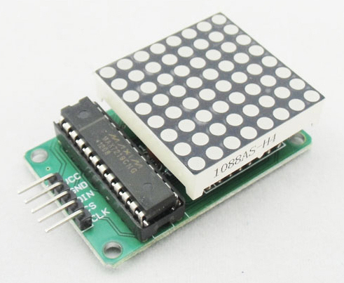
The 8 x 8 LED matrix is connected to the MAX 7219 as shown in the
circuit diagram and the data input is received from the Arduino board to
the MAX 7219.
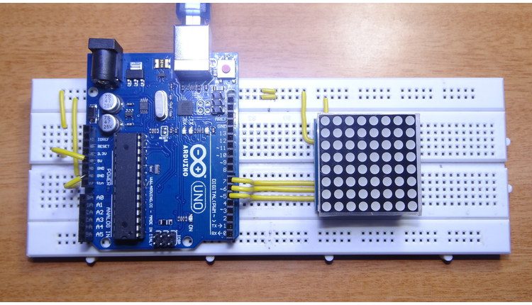
NOTE:
Pre-wired MAX 7219 and 8 x 8 LED matrix modules are available in the market. They can be used for convenience.
Working
The aim of the project is to interface an Arduino Uno board with an 8 x 8 LED matrix to display information.
Even though a single 8 x 8 LED matrix with corresponding MAX 7219 IC
is used in this project, multiple LED matrices can be connected in
series for long scrolling display. Connect the components as shown in
the circuit diagram. The working of the system is as follows.
3 of the 14 available digital input / output pins are used to control
the display driver IC MAX 7219. The 3 pins on the MAX7219 IC are clock,
data in and load (or cs in case of MAX 7221 IC). A maximum clock
frequency of 10MHz can be applied. DIN (Data in) accepts the serial data
from the microcontroller or Arduino board.
It is 16 bit long where the first 8 bits (D0 – D7) are for driving
the columns (SEG A-G and DP of the MAX 7219 IC) of the LED matrix and
the next 8 bits (D8 – D15) are for driving the (DIG 0-7 of the MAX 7219
IC) rows of the LED matrix.
The load pin (or CS or chip select pin in case of Max 7221 IC) latches the serial input data on its rising edge.
Another important pin on MAX 7219 is the ISET, which sets the peak
current to the segment to drive all the LEDs. It is connected via a
resistor (R1), which is called RSET. The capacitors filters out any
noise in the supply.
When the serial data in is sent using the Arduino (through the
program), the serial data is converted into segments and digits to drive
columns and rows of the LED matrix. According to the data sent, the
corresponding LEDs on the matrix light up and display the message.
The program written here is for scrolling text display. It might be
difficult to view long scrolling data on a single 8 x 8 LED matrix.
Hence, multiple LED matrices can be chained to form a long matrix.
The no. of MAX 7219 ICs are equal to the no. of 8 x 8 LED matrices.
In order to extend the display to multiple LED matrices, the Data OUT
(DOUT) pin of the first MAX 7219 must be connected to the Data IN (DIN)
pin of the second MAX 7219 IC. This process must be continued for
multiple LED matrices.
(The positioning of the LED Matrix in the chain is important. The first LED matrix must be placed at the right of the chain.)
The program uses a library called LedControl. This library must be
added to the Arduino IDE and the header file LedControl.h must be
included in the program.
The use of this library file is to enable multiple MAX 7219 ICs to
be integrated and also provide scrolling text. The library can be
downloaded from this link.
More and more makerspaces around the world are looking to add coding and electronics to their maker education programs. One of the best ways to do this is by integrating an Arduino board into makerspace projects and lessons. We’ve found that a lot of maker educators haven’t taken the plunge into coding or Arduino because they think programming is scary. Because of this, we wanted to make sure this tutorial was written for the absolute beginner with no experience whatsoever. This tutorial is a high level view of all the parts and pieces of the Arduino ecosystem. In future posts, we will take you step by step in creating your first simple Arduino project. What Is Arduino? Arduino is an open source programmable circuit board that can be integrated into a wide variety of makerspace projects both simple and complex. This board contains a microcontroller which is able to be programmed to sense and control objects in the physi...
GSM Based Home Security Alarm System Using Arduino Home Security Systems are an important feature of modern residential and office setups. Home security systems must be affordable, reliable and effective. Modern complex home security systems include several security features like fire, intruders, electronic door lock, heat, smoke, temperature, etc. Some security systems may be a combination of all the security measures. Such complex systems may be expensive and may not be affordable by everyone. There are individual security systems based on the requirement. In this project, we designed a simple but very efficient home security that has a function of calling the homeowner on his/her mobile number in case of an intruder alert. Help us in selecting the next DIY Arduino Project. : Select your Favourite Project » The project is based on Arduino, PIR motion detection sensor and GSM Module. Table of Contents Circuit Diagram Hardware Required Circuit ...
Arduino Solar Tracker In modern solar tracking systems, the solar panels are fixed on a structure that moves according to the position of the sun. Let us design a solar tracker using two servo motors, a light sensor consisting of four LDRs and Arduino UNO board. Table of Contents Circuit Diagram Components Required Working Setup Project Code Circuit Diagram The circuit design of solar tracker is simple but setting up the system must be done carefully. Four LDRs and Four 100KΩ resistors are connected in a voltage divider fashion and the output is given to 4 Analog input pins of Arduino. The PWM inputs of two servos are given from digital pins 9 and 10 of Arduino. Components Required Arduino UNO [ Buy Here ] Servo Motor [ Buy Here ] Light Sensors LDR Resistors Working LDRs are used as the main light sensors. Two servo motors are fixed to the structure that holds the solar panel. The program for Arduino is uploaded to the microcontroller. Th...


Comments
Post a Comment