7
Segment LED displays are used in many applications as front panel
number indicators. The most common applications are calculators,
microwave ovens, electronic lab equipment like function generators and
frequency counters.
A 7 segment LED display consists of 7 LEDs arranged in such a way
that it can display numbers from 0 to 9. The arrangement of LEDs in the
display can be either common anode or common cathode.
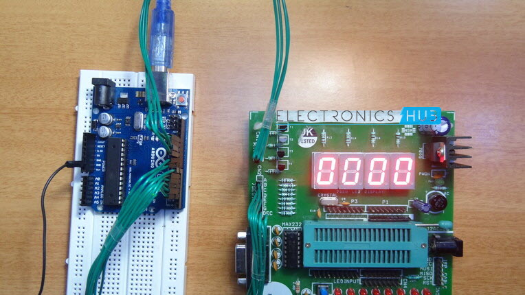
In this project, a 4 – digit 7 – segment LED display is used to display numbers using Arduino.
Either a compact module containing four 7- segment LED displays can
be used or four individual 7 – segment displays can be used by
multiplexing them.
4 – Digit compact 7 – segment LED display — 1(Or)7 – Segment LED display — 4
BC547 — 4
1KΩ — 4
100Ω — 4
Working of 4 – Digit 7 – Segment LED Display
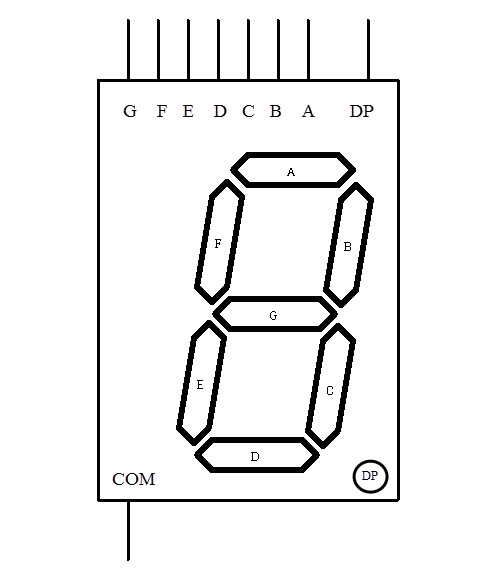
A 7 – Segment LED display, as the name indicates, is an assembly of
LED bars, where each bar can be powered individually. Each LED bar is in
the form of a hexagon and the overall arrangement will be in the form
of ‘8’.
The following figure shows a general representation of 7 – segment LED display with dedicated names to each segment.
Each segment can be powered separately to display digits from 0 to 9.
The following figure shows the pattern of digits displayed by a 7 –
segment LED display.
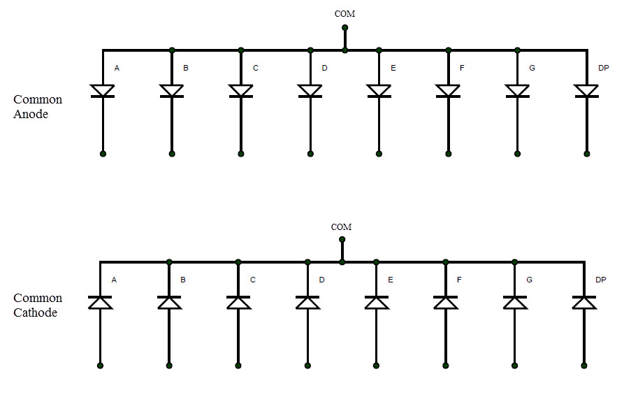
As mentioned earlier, in a 7 – segment display, the LEDs can be arranged in common anode or common cathode mode.
The equivalent circuit of a 7 – segment display in common anode and common cathode configuration is shown below.
To determine whether the 7 – segment display is common anode or
cathode, a small test circuit can be built. The common terminal of the
display is connected to a current limiting resistor.
The resistor is given positive voltage and any of the segments (A to
G) is connected to ground. If the segment glows, then it is common anode
display.
If the segment doesn’t glow, reverse the polarity of the supply and then it glows. This is a common cathode display.
It is important to determine whether the display is of common anode
or common cathode type as the code for Arduino (or any microcontroller)
will depend on it.
In this project, we are using a 4 – digit 7 – segment LED display. We
can use a compact 4 – digit module or use four individual 7 – segment
displays and multiplex them to make a 4 – digit display.
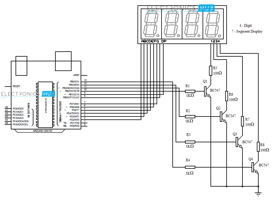
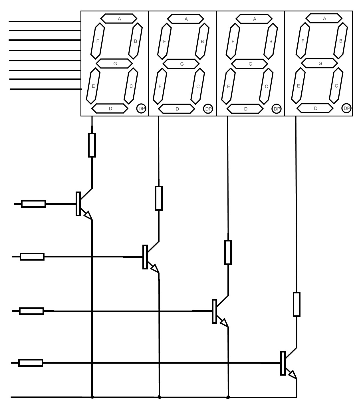
The following figure shows four multiplexed 7 – segment LED displays.
Respective segment pins (A to G and DP) of all the 7 – segment displays are connected with each other.
Hence, only 8 pins will be sufficient to control all the eight
segments of all four displays. These eight pins are connected to eight
pins of Arduino.
We assume that the selected 7 – segment module is of common cathode
type. The four common pins from four displays are connected to collector
terminals of four different transistors through current limiting
resistors.
The emitter terminals of four transistors are connected to ground.
The four base terminal of the four transistors are connected to four
pins of Arduino through current limiting resistors.
All the connections are shown in the circuit diagram.
The aim of this project is to demonstrate the working of a 4 – digit 7
– segment LED display using Arduino by implementing a simple counter.
The circuit diagram and written code are developed for common cathode type 7 – segment LED display.
Code
#define duration 5000
#define A 2
#define B 3
#define C 4
#define D 5
#define E 6
#define F 7
#define G 8
#define DP 9
#define disp1 10
#define disp2 11
#define disp3 12
#define disp4 13
#define numbersegments { \
{1,1,1,1,1,1,0,0},\
{0,1,1,0,0,0,0,0},\
{1,1,0,1,1,0,1,0},\
{1,1,1,1,0,0,1,0},\
{0,1,1,0,0,1,1,0},\
{1,0,1,1,0,1,1,0},\
{1,0,1,1,1,1,1,0},\
{1,1,1,0,0,0,0,0},\
{1,1,1,1,1,1,1,0},\
{1,1,1,0,0,1,1,0},\
}
byte numbers[10][8] = numbersegments;
const int segments[8] = {A, B, C, D, E, F, G, DP};
void setup()
{
pinMode(A, OUTPUT);
pinMode(B, OUTPUT);
pinMode(C, OUTPUT);
pinMode(D, OUTPUT);
pinMode(E, OUTPUT);
pinMode(F, OUTPUT);
pinMode(G, OUTPUT);
pinMode(DP, OUTPUT);
pinMode(disp1, OUTPUT);
pinMode(disp2, OUTPUT);
pinMode(disp3, OUTPUT);
pinMode(disp4, OUTPUT);
digitalWrite(A, LOW);
digitalWrite(B, LOW);
digitalWrite(C, LOW);
digitalWrite(D, LOW);
digitalWrite(E, LOW);
digitalWrite(F, LOW);
digitalWrite(G, LOW);
digitalWrite(DP, LOW);
digitalWrite(disp1, LOW);
digitalWrite(disp2, LOW);
digitalWrite(disp3, LOW);
digitalWrite(disp4, LOW);
}
void loop()
{
for (int digit4=0; digit4<10; digit4++)
{
for (int digit3=0; digit3<10; digit3++)
{
for (int digit2=0; digit2<10; digit2++)
{
for (int digit1=0; digit1<10; digit1++)
{
for (int t=0; t<30; t++)
{
setsegments(digit1, disp1, duration);
setsegments(digit2, disp2, duration);
setsegments(digit3, disp3, duration);
setsegments(digit4, disp4, duration);
}
}
}
}
}
}
void setsegments(int number, int digit, int ontime)
{
for (int seg=0; seg<8; seg++)
{
if(numbers[number][seg]==1)
{
digitalWrite(segments[seg], HIGH);
}
else
{
digitalWrite(segments[seg], LOW);
}
}
digitalWrite(digit, HIGH);
delayMicroseconds(ontime);
digitalWrite(digit, LOW);
}
You are free to use above code. Feel free to ask your doubts and
questions in below comment. Our technical person love to help you.
More and more makerspaces around the world are looking to add coding and electronics to their maker education programs. One of the best ways to do this is by integrating an Arduino board into makerspace projects and lessons. We’ve found that a lot of maker educators haven’t taken the plunge into coding or Arduino because they think programming is scary. Because of this, we wanted to make sure this tutorial was written for the absolute beginner with no experience whatsoever. This tutorial is a high level view of all the parts and pieces of the Arduino ecosystem. In future posts, we will take you step by step in creating your first simple Arduino project. What Is Arduino? Arduino is an open source programmable circuit board that can be integrated into a wide variety of makerspace projects both simple and complex. This board contains a microcontroller which is able to be programmed to sense and control objects in the physi...
GSM Based Home Security Alarm System Using Arduino Home Security Systems are an important feature of modern residential and office setups. Home security systems must be affordable, reliable and effective. Modern complex home security systems include several security features like fire, intruders, electronic door lock, heat, smoke, temperature, etc. Some security systems may be a combination of all the security measures. Such complex systems may be expensive and may not be affordable by everyone. There are individual security systems based on the requirement. In this project, we designed a simple but very efficient home security that has a function of calling the homeowner on his/her mobile number in case of an intruder alert. Help us in selecting the next DIY Arduino Project. : Select your Favourite Project » The project is based on Arduino, PIR motion detection sensor and GSM Module. Table of Contents Circuit Diagram Hardware Required Circuit ...
Arduino Solar Tracker In modern solar tracking systems, the solar panels are fixed on a structure that moves according to the position of the sun. Let us design a solar tracker using two servo motors, a light sensor consisting of four LDRs and Arduino UNO board. Table of Contents Circuit Diagram Components Required Working Setup Project Code Circuit Diagram The circuit design of solar tracker is simple but setting up the system must be done carefully. Four LDRs and Four 100KΩ resistors are connected in a voltage divider fashion and the output is given to 4 Analog input pins of Arduino. The PWM inputs of two servos are given from digital pins 9 and 10 of Arduino. Components Required Arduino UNO [ Buy Here ] Servo Motor [ Buy Here ] Light Sensors LDR Resistors Working LDRs are used as the main light sensors. Two servo motors are fixed to the structure that holds the solar panel. The program for Arduino is uploaded to the microcontroller. Th...


Comments
Post a Comment